Temperature represents roughly 40% of all industrial process measurements, and among the sensors making those measurements, resistance temperature detectors hold a specific reputation: they are the most accurate thermometers routinely used in industrial and laboratory settings, capable of achievable uncertainties as low as ±0.001°C under controlled conditions. That precision is exactly why sloppy calibration or improper wiring can undo an RTD's core advantage entirely.
This is why RTD calibration UAE process industries, laboratories, and pharmaceutical facilities depend on demands more attention to wiring configuration and methodology than most other temperature sensor types. This guide covers how RTDs actually work, why wiring configuration matters as much as the calibration itself, and what a proper verification process looks like.
How RTDs Actually Measure Temperature
A resistance temperature detector uses the predictable relationship between a platinum element's electrical resistance and its temperature. A PT100 sensor is defined to read exactly 100 ohms at 0°C, while a PT1000 reads 1,000 ohms at the same reference point, both following the internationally standardized temperature coefficient defined under IEC 60751. As temperature rises, resistance increases in a well-characterized, highly repeatable pattern, which is precisely what makes RTDs so much more accurate and stable than thermocouples across their more limited but higher-precision operating range.
Why Wiring Configuration Is Central to RTD Accuracy
Unlike most other temperature sensors, an RTD's accuracy depends heavily on how it's physically wired into the measurement circuit, not just the quality of the sensing element itself. This is because the measuring circuit doesn't only measure the resistance of the platinum sensing element, it can also inadvertently measure part or all of the resistance of the connecting lead wires themselves, introducing error that has nothing to do with actual temperature.
2-Wire Configuration
The simplest wiring method, where lead wire resistance adds directly to the sensor's measured resistance, causing a reading higher than the true value. This error grows with cable length, making 2-wire configurations suitable only for short cable runs where high precision isn't required.
3-Wire Configuration
The most widely used configuration in industrial process control, using a third wire to measure and compensate for lead wire resistance, assuming both lead wires carry equal resistance. This offers a practical balance between cost and accuracy, adequate for most general industrial applications.
4-Wire (Kelvin) Configuration
The gold standard for laboratory and calibration work, using separate pairs of wires for current supply and voltage sensing. Because the voltage-sensing leads carry virtually no current, their resistance has negligible effect on the measurement, making 4-wire configuration the only method that genuinely eliminates lead wire resistance as a source of error, regardless of cable length or condition.
The practical stakes here are significant: a single ohm of uncompensated lead resistance causes approximately 2.6°C of error on a PT100 sensor, an error large enough to completely undermine the precision an RTD is specifically chosen to provide.
Tolerance Classes Under IEC 60751
IEC 60751 defines four tolerance classes for RTD sensors, each specifying a different accuracy requirement at the 0°C reference point:
- Class AA: ±0.10°C, the tightest tolerance, typically requiring 4-wire measurement and precision reference equipment to properly verify
- Class A: ±0.15°C, also generally requiring 4-wire configuration for calibration to properly characterize
- Class B: ±0.30°C, the most common industrial grade, calibratable using a precision digital multimeter with 4-wire capability
- Class C: ±0.60°C, the loosest tolerance class, suited to general-purpose temperature monitoring where tight accuracy isn't critical
Understanding which class a given sensor is rated to matters both for selecting appropriate reference equipment during calibration and for setting realistic expectations about achievable accuracy in the field.
How RTD Calibration Actually Works
A proper calibration process, following IEC 60751 and ISO/IEC 17025 documentation requirements, generally follows this sequence:
- Documenting the sensor's as-found condition exactly as received, since this data establishes whether any process or product measured since the last calibration remained within specification
- Allowing all equipment, including the reference bath or dry block, to reach thermal equilibrium, typically requiring at least 30 minutes of stabilization time
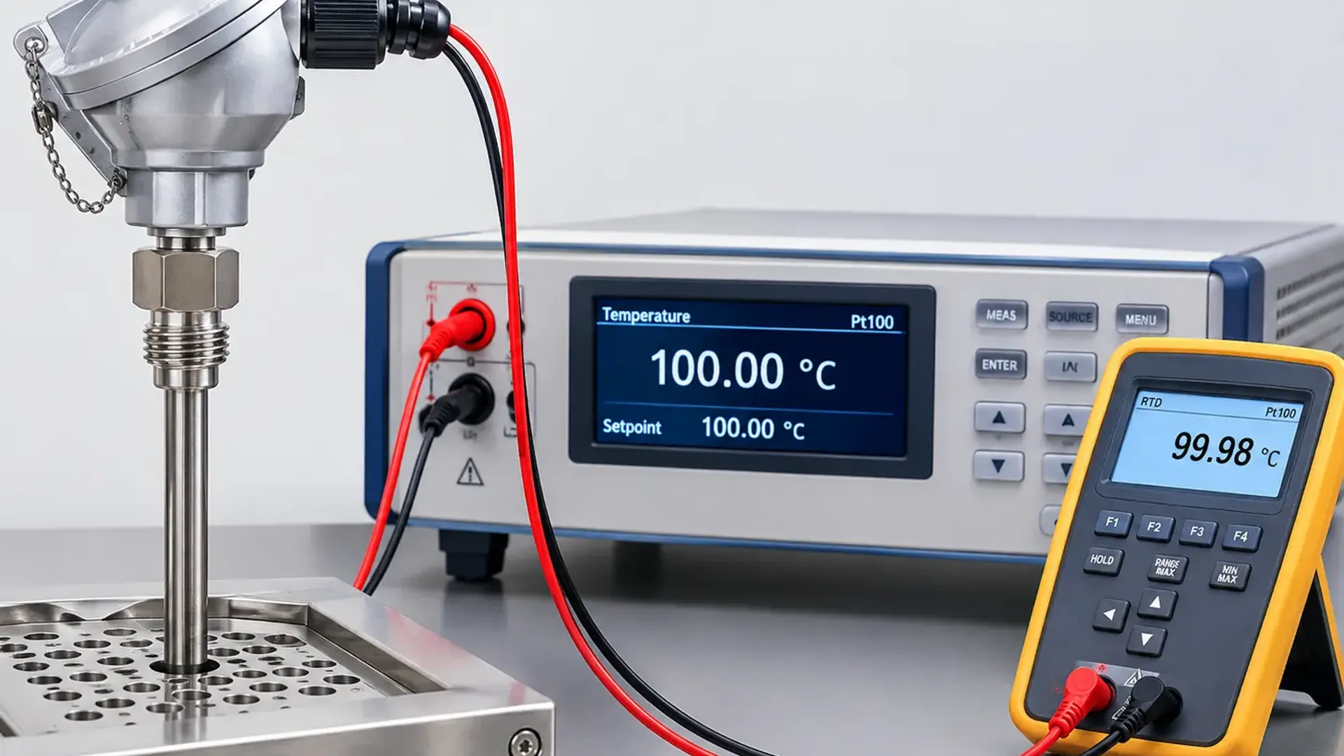
- Connecting the RTD using a 4-wire (Kelvin) configuration wherever the sensor and application support it, with separate current and voltage-sensing leads
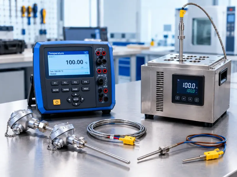
- Immersing the RTD in a controlled reference source, either a liquid bath or dry block calibrator, alongside a certified reference thermometer
- Measuring resistance at multiple temperature points across the sensor's actual operating range, converting each measured resistance to a temperature deviation using the sensor's known resistance-temperature coefficient
- Comparing each measured deviation against the tolerance limit defined for the sensor's rated class
- Documenting results, including the reference standards used and the measurement uncertainty achieved
For the highest-accuracy Class A and AA sensors, calibration typically requires a precision resistance bridge with uncertainty below 10 ppm, rather than a standard digital multimeter, which is generally sufficient only for Class B verification work.
Why As-Found Documentation Matters So Much for RTDs
Recording an RTD's condition exactly as it arrived for calibration, before any adjustment, is a regulatory requirement rather than an optional nicety. This as-found data is what allows a facility to determine whether any measurements or products made since the sensor's last calibration were genuinely within specification, directly supporting ISO 9001 Clause 7.1.5.2 requirements around nonconforming measuring equipment, and equally relevant to FDA 21 CFR Part 211.68 compliance for pharmaceutical manufacturing environments.
RTDs vs Thermocouples: When Each Makes Sense
Facilities running both RTDs and thermocouples benefit from understanding when each technology is the better fit. RTDs generally offer superior accuracy and long-term stability within a more limited temperature range, typically well suited to process temperatures below around 600°C, while thermocouples handle a much wider range extending to far higher temperatures but with generally looser accuracy. For applications where achievable precision genuinely matters and the operating temperature falls within an RTD's practical range, the RTD is usually the better instrument choice, provided its wiring is configured correctly to preserve that precision advantage.
ISO 17025 Accredited RTD Calibration
Our temperature calibration services cover RTDs alongside thermocouples, infrared thermometers, and dry block calibrators under full EIAC ISO 17025 accreditation, with 4-wire precision measurement capability supporting Class B and higher accuracy verification across the temperature ranges these sensors are designed for.
What an RTD Calibration Certificate Should Include
A properly issued calibration certificate should clearly document:
- The specific sensor make, model, type (PT100 or PT1000), and serial number
- The wiring configuration used during calibration, 2-wire, 3-wire, or 4-wire
- Measurement results at each tested temperature point, including as-found and as-left data
- The sensor's tolerance class and pass or fail status against that class
- The measurement uncertainty associated with the calibration
- The accreditation body and standard the issuing laboratory operates under
Frequently Asked Questions
Why does RTD wiring configuration matter for calibration accuracy? Lead wire resistance can add directly to the sensor's measured resistance, introducing temperature error unrelated to the actual sensing element. A 4-wire configuration eliminates this error entirely, while 3-wire compensates for it approximately, and 2-wire does not compensate at all.
How much error can lead wire resistance actually cause? A single ohm of uncompensated lead resistance causes approximately 2.6°C of error on a PT100 sensor, an error large enough to defeat the purpose of using a high-accuracy RTD in the first place.
What is the difference between a PT100 and PT1000 sensor? A PT100 reads 100 ohms at 0°C while a PT1000 reads 1,000 ohms at the same point, both following the same IEC 60751 standard temperature coefficient, with PT1000 sensors offering a stronger signal that can be advantageous over longer cable runs.
Which IEC 60751 tolerance class requires 4-wire measurement for calibration? Class AA and Class A sensors, with tolerances of ±0.10°C and ±0.15°C respectively, generally require 4-wire measurement and precision reference equipment. Class B, at ±0.30°C, can typically be verified with a calibrated digital multimeter offering 4-wire capability.
Why is as-found data required before any calibration adjustment? As-found data documents the sensor's actual condition before correction, establishing whether measurements or products made since the previous calibration were within specification, a requirement under ISO 9001 and relevant to FDA compliance in regulated manufacturing environments.
Closing Thoughts
RTD calibration UAE process industries, laboratories, and pharmaceutical facilities depend on protects one of the most accurate temperature sensing technologies available, provided both the calibration methodology and the wiring configuration are handled correctly. Given how easily lead wire resistance can silently undermine an RTD's inherent precision, proper 4-wire calibration against IEC 60751 tolerance classes is what keeps that accuracy genuinely realized in practice, not just on paper.
To schedule RTD or broader temperature calibration across the UAE, reach out through the General Tech Services contact page, or explore the full range of ISO 17025 accredited calibration disciplines covering temperature, pressure, dimensional, and electrical measurement.