
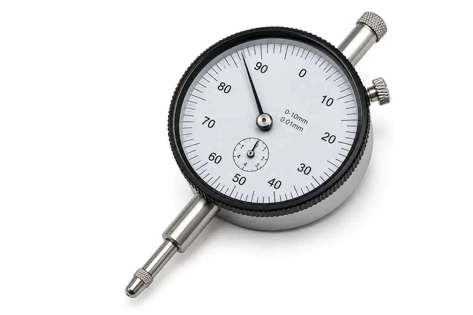
A dial indicator converts a tiny, otherwise invisible movement into a readable number, which is exactly why it shows up everywhere from machine alignment work to runout inspection to final quality checks on finished parts. That translation from motion to reading relies on an internal gear train that, like any mechanical system, wears and drifts over time. When it does, the dial keeps producing confident-looking numbers that simply aren't true anymore.
This is why dial indicator calibration UAE manufacturing, machining, and inspection facilities rely on needs to test more than just whether the needle moves. This guide covers what a proper dial indicator calibration actually verifies, the standard governing the process, and how often these instruments should be checked.
What a Dial Indicator Actually Measures
A dial indicator, sometimes called a dial gauge, is a precision mechanical instrument that measures small linear displacements with high resolution, converting minute movement of a spring-loaded plunger or lever into a readable position on a graduated dial face. This makes it indispensable across quality control, machine alignment, runout inspection, and general dimensional verification in manufacturing, aerospace, and automotive work.
Because the instrument depends on an internal gear and pinion mechanism to translate linear movement into rotational dial motion, its accuracy is vulnerable to a specific set of wear-related failure modes that a simple visual check will not reveal.
The Three Characteristics Every Calibration Must Verify
A proper dial indicator calibration evaluates three distinct metrological characteristics, not just a single accuracy figure:
Accuracy
How closely the indicator's displayed reading matches the true, actual displacement of the plunger or contact point. This is tested by displacing the spindle to known positions using a calibrated reference and comparing the dial reading against that known value.
Repeatability
Whether the instrument returns the same reading when measuring the same distance multiple times under identical conditions. Poor repeatability often points to worn internal gearing or excessive mechanical play that a single accuracy check would not necessarily catch.
Hysteresis
The difference in readings when the contact point approaches a given position from two different directions, one where the previous reading was smaller and one where it was larger. Hysteresis reflects internal friction or mechanical play in the gear train, and it is particularly important for dial indicators because this type of error can be completely invisible if a technician only ever checks displacement moving in a single direction.
A dial indicator can pass a basic accuracy check while still failing badly on repeatability or hysteresis, which is exactly why all three characteristics need independent verification rather than treating a single spot check as sufficient.
The Standard Behind Dial Indicator Calibration: ASME B89.1.10M
ASME B89.1.10M is the primary standard governing dial indicators for linear measurement, providing the essential requirements manufacturers and calibration laboratories use as a common technical reference. The standard defines:
- Accuracy, repeatability, and hysteresis limits appropriate to the indicator's stated grade and resolution
- Standardized test methods specifying how measurements should be taken across the instrument's range
- Classification and grading criteria, allowing users to select instruments appropriate to their required precision level, whether for general shop use or higher-accuracy inspection work
- Guidance on environmental conditions, since temperature, mounting rigidity, and measurement direction can all meaningfully influence results
Working to this standard ensures dial indicator calibration results are consistent and comparable regardless of which laboratory performs the work or which brand of indicator is being tested.
How Dial Indicator Calibration Actually Works
A thorough calibration process generally follows this sequence:
- Visual inspection of the crystal, bezel, stem, and contact point for damage, contamination, or stickiness affecting free movement
- Cleaning the unit to ensure the mechanism moves freely without internal resistance affecting results
- Rigid mounting on a comparator stand, with the indicator allowed to thermally acclimate to a standard reference temperature, typically 20°C, before testing begins
- Zeroing the dial against a reference surface or master gauge block
- Displacing the spindle at defined intervals across the indicator's range, commonly at 25%, 50%, 75%, and 100% of full travel, using Grade 0 or equivalent precision gauge blocks as the reference standard
- Testing hysteresis by comparing readings taken as the spindle approaches each point from opposite directions
- Repeating measurements at the same points multiple times to evaluate repeatability
- Comparing all results against the tolerance limits defined for the indicator's grade under ASME B89.1.10M
If measured errors fall within the applicable limits, a calibration certificate is issued documenting the deviations found and confirming traceability to national or international measurement standards.
Why Environmental Control Matters More Than It Seems
Dial indicators are sensitive enough that seemingly minor environmental factors can measurably affect calibration results. Temperature is the most significant of these, since both the indicator and the gauge blocks used as reference standards expand and contract with temperature changes, which is why calibration is performed at a controlled reference temperature rather than whatever ambient conditions happen to exist in a general workshop. Mounting rigidity also matters, since any flex or movement in how the indicator is held during testing introduces error that has nothing to do with the instrument's actual internal accuracy.
Calibration Intervals for Dial Indicators
General guidance for dial indicator calibration frequency includes:
- Calibration when the instrument is first purchased, establishing a documented baseline before it enters regular service
- Annual calibration thereafter as a standard baseline for most laboratory and general inspection use
- Six-month intervals for indicators used heavily in production environments where wear accumulates faster
- Immediate recalibration after any drop, suspected damage, or unexplained measurement inconsistency
Instruments used for runout inspection or machine alignment work, where accuracy directly affects downstream mechanical assembly quality, often warrant the shorter end of this interval range given how much other work depends on their continued accuracy.
Traceability and Why It Matters for Dial Indicator Results
Traceability is one of the most critical aspects of dial indicator calibration, since results need to be traceable to recognized national or international standards to hold any real credibility. This means the gauge blocks used as reference standards during calibration must themselves be properly calibrated and traceable, and professional calibration laboratories maintain a documented hierarchy of reference standards with known uncertainties significantly smaller than the tolerance of the instrument being tested.
Our dimensional calibration services cover dial indicators alongside calipers, micrometers, gauge blocks, and CMMs under full EIAC ISO 17025 accreditation, ensuring the same traceable reference standards support your entire dimensional metrology program.
What a Dial Indicator Calibration Certificate Should Include
A properly issued dial indicator calibration certificate should clearly document:
- The specific instrument make, model, and serial number
- Accuracy results at each tested point across the instrument's range
- Repeatability results from repeated measurements at the same points
- Hysteresis results comparing readings from opposite approach directions
- The applicable ASME B89.1.10M grade and tolerance limits used for pass or fail determination
- Traceability details for the reference gauge blocks used
- The accreditation body and standard the issuing laboratory operates under
If a certificate only confirms a general pass or fail without documenting these individual characteristics, it does not provide enough detail to judge the instrument's actual performance across its range.
Frequently Asked Questions
What is the difference between accuracy and repeatability in dial indicator calibration? Accuracy measures how closely the dial's reading matches the true displacement value, while repeatability measures whether the instrument returns the same reading when checking the same distance multiple times. An indicator can be reasonably accurate on average while still having poor repeatability due to internal mechanical play.
Why does hysteresis matter for dial indicators specifically? Hysteresis reflects internal friction or mechanical play in the gear train, showing up as a difference in readings depending on which direction the contact point approached from. This type of error can be completely missed if testing only checks displacement moving in a single direction.
How often should a dial indicator be calibrated? Dial indicators should be calibrated when purchased and annually thereafter as a general baseline, with more frequent calibration, often every six months, recommended for indicators used heavily in production environments.
What reference standard is used to calibrate a dial indicator? Precision gauge blocks, typically Grade 0 or equivalent, are the standard reference used, with the indicator's spindle displaced to known positions using these blocks to verify accuracy, repeatability, and hysteresis.
Does temperature really affect dial indicator calibration results? Yes. Both the dial indicator and the gauge blocks used as reference standards can expand or contract with temperature changes, which is why calibration is performed at a controlled reference temperature rather than uncontrolled ambient shop conditions.
Closing Thoughts
Dial indicator calibration UAE manufacturing and inspection facilities depend on protects the accuracy of one of the most widely used precision instruments on any shop floor. Verifying accuracy, repeatability, and hysteresis together, against the ASME B89.1.10M standard and with properly traceable reference standards, is what keeps every runout check, alignment reading, and dimensional inspection built on that dial indicator defensible.
To schedule dial indicator or broader dimensional calibration across the UAE, reach out through the contact page, or explore the full range of ISO 17025 accredited calibration disciplines covering dimensional, electrical, pressure, and temperature measurement.